- Original Paper
- Open access
- Published:
A generalized IC engine propulsion method and corresponding transmission design for improving vehicle fuel efficiency
European Transport Research Review volume 6, pages 225–239 (2014)
Abstract
Based on the analysis of the working profiles of internal combustion (IC) engines, a case-emphasized propulsion method is generalized to improve vehicle fuel efficiency. With this method, the ratio of the most-used speed to the most-desired speed of an IC engine is employed to control the engine to always run at its optimal working state with an efficient single-stage gear transmission. Examples of the propulsion method with different brands of IC engines in the market place demonstrate the potential that this method could reduce engine fuel consumption up to 5 ~ 39 %. A conceptual design of n-ratio automatic single-stage gear transmission is then developed to implement the case-emphasized propulsion method in a general way. Not only can such a design execute the proposed propulsion method well as an almost continuous variable transmission, but it can also increase the propulsion efficiency about 8 ~ 18 % if it is applied to replace the traditional automatic transmissions or continuously variable transmissions (CVTs) in vehicle drivetrains.
1 Background
Because of the shortage of crude oil and the concern of environment, the automotive industry is required to ramp up production of more fuel-efficient vehicles on a tight timeline. As an essential power conversion system for vehicle propulsion, the technology of internal combustion (IC) engine is the focus of attention for attempting the improvement of vehicle efficiency. It is known that the technology of IC engine has its advantages as compared with other energy conversion technologies used on vehicles:
-
The IC engine is a proven cost-effective technology with a long history of dominating the markets of power generation, indicating that the technology has stood firm with the test of time.
-
Different from other indirect technologies which convert fuel in the way of heat energy → electrical energy → mechanical energy or chemical energy → electrical energy → mechanical energy, an IC engine can directly convert the heat energy of fuel → mechanical energy; thus, it avoids the reduction of fuel efficiency during the process of conversion.
-
It possesses competitive ratios of power/weight and power/volume.
-
It can also run without pollution if proper fuel is used.
-
Even if fossil fuel is used up in the future, it can easily find non-fossil fuel as replacement. As a result, it will smoothly transfer the fossil fuel era into the non-fossil fuel era with a convenient and inexpensive change of the power-generating method.
Unfortunately, the fuel efficiency of an IC engine is still low. An IC engine may only run at around 30 % of fuel efficiency. For decades, scientists have devoted great efforts to improve the efficiency of IC engines in deliberating of many different approaches. Currently, the general ways to improve the fuel efficiency of IC engine may be understood from Taylor’s work [1]. To have overall understanding of the current IC engine technology, Taylor conducted a systematic review of the IC engine technology. He suggested that there could be 6–15 % improvement in internal combustion fuel efficiency in the coming decade. Taylor stated that developments beyond the next decade were likely to be dominated by four topics:
-
Emission legislation and emission control,
-
New fuels,
-
Improved combustion; and
-
Advanced concepts for energy saving
It is considered that IC engines could achieve higher efficiency to meet the requirements of the raised standards with the development of new technology in the above four topics. However, with the investigation of prior arts, it is believed that at least one more topic may also be considered as an important way to improve the performance of IC engines, that is, the topic of increasing the fuel efficiency of IC engines with its application. It is known that the fuel efficiency of an IC engine is not only related to the efficiency of the engine itself but also related to the efficiency of how it works. If a high-efficient engine is arranged to run in an improper situation, the fuel efficiency in application will remain low.
It is acknowledged that an IC engine could run at its most efficient state at certain range of engine speeds of revolution per minute (RPM) which produces peak power, maximizing fuel efficiency by always allowing the engine to run at the RPM (http://en.wikipedia.org/wiki/Continuously_variable_transmission). For decades, scientists have tried to find the best way to use the concept for better fuel efficiency. The trend of how to use the working properties of an IC engine to achieve optimal fuel efficiency can be understood by following concise discussions of prior arts:
-
Osman et al. noted that it was possible to improve the efficiency of conventional vehicles by intelligent control of the drivetrain. They therefore modeled IC engines using neural networks for fuel saving by intelligent control of the transmission. The Initial results they presented showed that considerable fuel savings could be achieved by intelligent selection of optimal shift points [2].
-
Maugham et al. considered that, due to low frictional and pumping losses, a gasoline engine’s fuel efficiency could be maximized at low speed, high torque conditions. They indicated that a continuously variable transmission (CVT) allowed a drivetrain controller the freedom to develop a required output power at a range of engine torque and speed conditions. This flexibility can be used to maximize fuel efficiency. Since controlling a gasoline engine in this range could compromise transient vehicle response, the preliminary work had been taken by them to investigate the potential of charge dilution to control steady state engine torque. The outcomes of their research showed the potential to maintain economy gains with a CVT drivetrain whilst improving a vehicle’s drivability [3].
-
Sasaki introduced Toyota’s new hybrid drivetrain system which included a drivetrain that consisted of a planetary gear mechanism for dividing the drive force and two motor/generators. Such a system is based on the concept that uses computer control to optimize engine fuel consumption and to minimize exhaust emissions [4].
-
Ariyono et al. presented their research about the continuously variable transmissions (CVT). They considered that CVT could provide a wider range transmission ratio, good fuel economy, smoothly shifting of ratio, and excellent drivability. They also noted that, with CVT, it was possible to maintain a constant engine speed based on either its optimum control line or maximum engine power characteristic. With their work, the use of Adaptive Neural Network Optimization Control (ANNOC) was brought in to indirectly control the engine speed by adjusting pulley CVT ratio [5].
-
Hayashi et al. developed a transmission controller for an automobile to deal with the issue of variable loads. Such a development is, actually, an automated manual gear-shift system. Neuro and fuzzy methods are adopted for the controller and the interface between a vehicle operator and an automobile to make the operator feel comfortable even when automobile loads change while traveling [6].
-
Scherer et al. introduced the six-speed automatic transmission for passenger cars developed by ZF in 2001. They mentioned that, with regard to the increasing requirements especially in reduction of CO2 emissions, a new eight-speed transmission is now under development in ZF. The main targets for this transmission family are a further significant reduction in fuel consumption and emissions, good driving performance and state-of-the-art driving comfort. The authors considered that the new developments showed that the technology of “conventional” automatic transmissions with torque converter and planetary gear sets still presented a lot of potential [7].
-
Lorenz et al. introduced that the BMW 750i had interconnected electronic systems to control the engine and the automatic transmission. They illustrated the concept and interplay of the drivetrain, the driving stability electronics, and the individual functions, and also described the measures taken to make the drive-management system reliable [8].
-
Bednarek et al. introduced GM’s new six-speed front wheel drive (FWD) family of automatic transmissions. They reported that the new transmission had a wide overall ratio spread of 6.1:1 which allowed for optimum adaptation of the drivetrain for various categories of vehicles. The authors considered that the use of the torque converter lockup clutch with electronically controlled slip could lead to the optimum use of the fuel in vehicles [9].
The following prior arts also conducted the investigation about the existing transmission and drivetrain technologies with corresponding analysis of fuel efficiency and prediction of the trends of future development.
-
HÖhn introduced the future trends of automotive drivetrains in Europe. He pointed out that automotive transmissions for passenger cars in Europe have changed continuously in the last 20 years. The ratio range for transmissions has increased more and more. He believed that the trend to more gears for automatic transmissions and manual gear boxes would be going on. He predicted that, in the future, different concepts would be the general trends, and semi-automated manual gearboxes, CVTs, and hybrid systems would be applied even though in the past there were only manual gearboxes and automatic transmissions on the market [10].
-
Wu and Sun introduced 5 major automated transmissions in international automobile markets regarding their working principles and development history as well as the state-of-the-art of the automated transmissions. Advantages and disadvantages of automated transmissions were compared, and development perspective was presented. For convenience, representative manufacturers and the application status in the Chinese market are listed [11].
-
Wu and Sun also investigated the development history and research status of continuously variable transmission (CVT). Particularly, they introduced the basic structure of metal v-belt CVT, and compared the structure and working principle of the metal belt and chain. With their research, the principle and performance of the mechanical-hydraulic control system and electro-hydraulic control system, especially the slip control strategy developed recently were explained, and future CVT development trend were predicted [12].
-
Buscemi discussed that, today, drivers could have more transmission options than before as automatics and manuals are accompanied by automated manuals (AMT), dual clutch transmissions (DCT), and continuously variable transmissions (CVT). The author stated that the most important objective and the main goal for transmission engineers would be to improve fuel efficiency and to perk up overall drivetrain efficiency by reducing drag losses [13].
-
Srivastava and Haque studied the significant developments of vehicle transmissions over the last two decades. They considered that a continuously variable transmission (CVT) would offer a continuum of gear ratios between desired limits, which would consequently enhance the fuel economy and dynamic performance of a vehicle by better matching the engine operating conditions to the variable driving scenarios. They mentioned that the potential of CVT had not been realized in the mass production of vehicle although it could play a crucial role to improve vehicle fuel economy, and discussed the challenges and critical issues for future research on modeling and control of CVTs [14].
-
Gilmore emphasized that efficiency goals could represent one of the key factors governing drivetrain choice. With specifying three developments, the conventional four-speed manual or automatic transmission was competed, and the fuel consumption associated with continuously variable ratio and infinitely variable ratio automobile transmissions were simulated in the situations of urban and highway constant-speed operation [15].
-
Amann reviewed the historical growth in average drivetrain efficiency of the US passenger-car fleet, and found that imposition of emission control caused a temporary retreat, but with the introduction of the catalytic converter, growth was restored to bring a dramatic decrease in exhaust emissions. He mentioned the dominant position of the gasoline engine and predicted the continuous improvement of transmission [16].
The prior arts show the essential ways to apply the aforementioned concept to improve the efficiency of an IC engine, i.e., the vehicle fuel efficiency, with the development of different control schemes and the introduction of new multiple-speed AMTs, DCTs, and various CVTs. However, through study of the prior arts, it raises some issues to be resolved below:
-
It is noted that the prior arts were developed with the concept to approach the optimal fuel efficiency by controlling the IC engine to run in the RPM range around the maximum power since the range is close to the congregation of the minimum fuel consumption. Such a concept may not always work because of the following reasons:The torque decreases with the increase of speed after the maximum torque is reached. Since the output power is the product of the two, the maximum power may almost keep unchanged in a large speed range of RPM. This means that there are many RPMs of maximum power; therefore, it is difficult to use the above-mentioned concept to approach the optimal fuel consumption.From the study of the working properties of IC engines, it is found that there are basically two different IC engine working profiles (Discussed in the next section). The first profile appears a congregation of the minimum fuel consumption RPM close to the maximum output torque RPM. The second profile appears no congregation of the minimum fuel consumption RPM near the maximum output torque RPM, and the fuel consumption rate simply rises with the increase of RPM. It means that the said concept of prior arts can only work with the first profile.
-
The prior arts did not identify the necessary condition to ensure that the control method is workable to control a particular IC engine in practice.
-
Even though the prior arts described that the use of CVTs could increase the fuel efficiency of an IC engine, they did not specify if CVTs could handle power transmission with satisfactory mechanical efficiency.
-
The prior arts did not present a case-emphasized propulsion control scheme to satisfy all primary needs for every single vehicle yielding the statistic data of the survey that how the vehicle could be used.
-
There is no claim of a n-ratio automatic transmission formed by n-pair of single-stage gears that has high mechanical efficiency to conveniently approach the case-emphasized propulsion control scheme with a generalized solution to take advantage of the IC engine’s working characteristics yielding the data of survey for all different cases, and at the same time, to provide a comfortable operation similar to the automatic transmission to make a gear transmission an almost CVT.
It is necessary to point out the fact that, so far, the fuel efficiency of an IC engine equipped on a vehicle copied with drivetrain (either traditional gearbox/clutch transmission or CVT) is yet to be satisfactory. It is considered that if the above issues can be resolved, it should lead to more efficient fuel consumption. In such a situation, it is necessary to comprehensively understand the IC engine working properties to conduct further development.
2 Discussions of the working profiles of IC engine
2.1 IC engine tests and the first working profile of IC engine
To ensure that an IC engine can constantly perform in the optimal working state, it is necessary to know the general relationships of the engine speed versus its fuel consumption and the engine speed versus its output torque. Such relationships can be basically learned through engine tests. Usually, there are two types of tests:
-
tests at variable speed, and
-
tests at constant speed
Further, the variable speed tests can be divided into full-load tests and partial-load tests. The constant speed tests are conducted mainly to determine specific fuel consumption. The following discussions give the basic ideas about the traditional engine tests.
-
I.
Variable-speed tests with spark-ignition (SI) engines
For the maximum power test on the SI engine, the throttle is fully opened and the lowest speed is maintained by the torque of the brake. When the engine is running in approximation of temperature equilibrium, the fuel consumption is detected. Figure 1 presents the record data of the variable-speed test for an automotive SI engine [17]. The profile in Fig. 1 is developed with the consideration of atmospheric conditions with the correction factor (CF).
Fig. 1 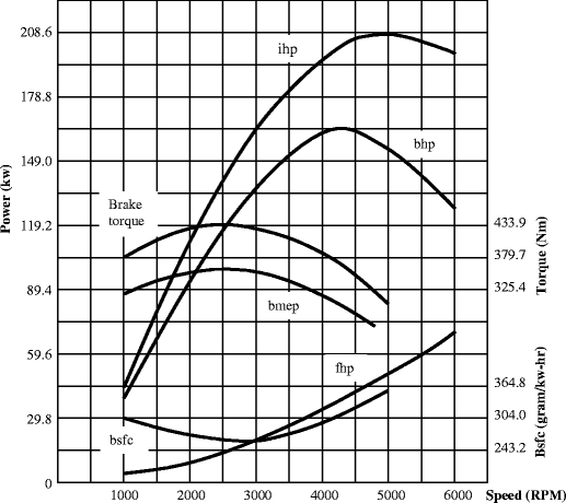
Variable-speed test of an automotive SI engine at wide-open throttle [18]
Refer to Fig. 1, it can be known that
-
the torque and mean effective pressure (bmep) are mountain-like curve versus speed;
-
the minimum specific fuel consumption (bsfc) is around the peak location of the mountain-like curve of the torque;
-
the friction horsepower (fhp) rises with the increase of speed, and it rises rapidly because of the reciprocating-piston mechanism;
-
the indicated horsepower (ihp) is the sum of the horsepower (bhp) and the friction horsepower, and the horsepower is the product of the torque and speed.
To conduct a partial-load at variable-speed, for example, 1/N of the load, the brake and throttle are adjusted to achieve 1/N of the maximum power at each speed. The curve of the brake horsepower versus speed could be obtained without running the test by merely dividing the maximum power by N. However, fuel consumption will vary in accordance with the changes of the load and throttle.
-
-
II.
Variable-speed test with the compression-ignition (CI) engine
It is more difficult to conduct the full-power test of a CI engine at variable speeds than the SI engine. Through the same procedure of the SI engine test, the brake torque is adjusted until the lowest operating speed is reached with the fuel pump injecting a quantity of fuel to make the exhaust gas slightly colored. This indicates that the engine is near the maximum load since some of the fuel is being wasted in smoke. This is used to define the full-load at different stages.
In the CI engine, there is no sharp limit and the color of exhaust smoke is a good way to identify the maximum load. The profile of CI engine tests is shown in Fig. 2 [17]. The fuel consumption curve in Fig. 2 shows that the minimum fuel consumption is around the midrange of the engine speed.
Fig. 2 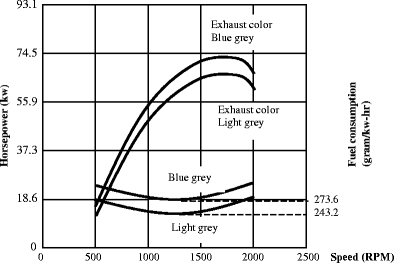
Variable-speed test of a CI engine with different interpretation of full load [18]
Variable-speed tests of a CI engine at part loads are done in the same way as a SI engine. It should be emphasized that the fuel consumption curve developed with either the full-load or the part-load tests can only be used for the case which has the same working condition and load as the tests; otherwise, the profile of tests can only be used as a rough reference.
With this kind of profile, the minimum fuel consumption RPM is close to the maximum output torque RPM which is usually the peak of power RPM. With the display of effective working range of the engine, the depicted profile of this kind of IC engine will demonstrate that the fuel consumption simply achieves the minimum value around the maximum torque RPM.
-
III.
The constant-speed test
A constant-speed test is done with a variable throttle from no-load to full-load to have smooth curves. Starting with no-load, the throttle is adjusted to get the designated speed. After the first run, the load is added and the throttle is opened wider to maintain the same speed. The test continues until the last run of the full-load is made with the wide-open throttle. In a CI engine test, the last test would have smoke in the exhaust gas.
With reference to the aforesaid engine tests and corresponding test data profiles, the relationship between the engine speed versus the torque and the fuel consumption can be generally described as follows:
-
At first, with the increase of the speed, the fuel consumption begins to drop and the torque begins to rise.
-
When the engine speed runs into some positions of the midrange, the fuel consumption drops to the minimum value and the torque reaches its peak.
-
After the engine runs over this midrange of speed, the fuel consumption will increase and the torque will decline with the continuous increase of speed.
Through the aforementioned tests, the following two kinds of profiles can be recorded to show the working properties of IC engines.
-


2.2 The first working profile of IC engine
The above profiles of Figs. 1 and 2 demonstrate the general properties of IC engine speed versus fuel consumption and torque through the tests for the SI type and CI type IC engines respectively [17]. Such working properties of an IC engine can be widely seen with the specifications of IC engines in the marketplaces (refer to Figs. 3 and 4). For better understanding, such a profile is defined as the first working profile of IC engine.

Specification profile of John Deere’s 6068 TF250 IC engine

Specification data and profile of DEUTZ’s BF4M2012 IC engine
2.3 The second working profile of IC engine
It is noted that there is still another kind of major working profile of an IC engine. For better understanding, this kind of profile is defined as the second profile of IC engine working properties. Figure 5 below shows the second working profile which is obtained with the tests of a Yanmar’s 4LHA-150 hp IC engine.

Specification data and profile of YANMAR’s 4LHA-150 hp Diesel Engine
This kind of depicted profile can be seen with the specifications of many brands of IC engines in the market place. With the second profile, the minimum fuel consumption RPM is far away from the maximum output torque RPM. Therefore, for effective demonstration of the working range, the depicted profile of this kind of IC engine will exhibit that the fuel consumption is up with the increase of the engine speed. Around the maximum torque, the fuel consumption rate is not close to the minimum value. As is mentioned previously, to control the IC engine running at the peak power RPM for minimum fuel consumption will not work with such a profile.
3 Propulsion method developed using the working profiles of IC engine
Based on the two kinds of working profiles of IC engines, a case-emphasized propulsion method can then be developed to achieve optimal fuel efficiency. To conduct the development, two terms are defined here for convenience:
-
First, it is known that, when an IC engine is applied for the propulsion of a vehicle, it may frequently do its regular work in several different working states. The frequently used working states are defined as the most-used working states. The speed and torque related to each of the most-used working states are defined as the most-used speed and the most-used torque.
-
Second, it is noticed that the most-used working states of an IC engine in a vehicle may be very different from its most-desired working state. The most-desired working state is the state that the engine conducts the least fuel consumption. The speed and torque related to the most-desired working state are defined as the most-desired speed and the most-desired torque correspondingly.
3.1 Case-emphasized propulsion method developed by using the first profile
With the above observation from Figs. 1, 2, 3, and 4, it is clear that, the output torque of an IC engine may achieve the maximum value at certain speed range that is near the speed of the least fuel consumption. This type of profile is identified as the first kind working profile of IC engine.
For better understanding of the working properties of an IC engine, the brake torque curve and bsfc curve in Fig. 1 are adopted here to conduct the following analysis (Fig. 6). Figures 1, 2, 3, 4 and 6 indicate how the use of the unique relationships among engine speed, output torque, and fuel consumption can improve fuel efficiency. In Fig. 6, it demonstrates that the least rate of fuel consumption is around the range from speed d1 to d2 with corresponding brake torque from k1 to k2. Generally, it is known that an IC engine may not necessarily work in such a range. For example, if the engine associated with Fig. 6 is frequently working in the speed range between e1 and e2 with mean torque of ke, then a case-emphasized propulsion method can be developed to make full use of the working properties of an IC engine.

Transmission speed and torque from engine shaft to gear pair shaft
3.1.1 Basic method of IC engine propulsion for improving fuel efficiency
With the case-emphasized propulsion method, in Fig. 6, the range (e1 – e2) is defined as the most-used speed range. The speed at point e is the mean of most-used speed, and it can be approximated by
In Fig. 6, the range (d1 – d2) is considered as the most-desired speed range since fuel consumption is the lowest when an engine runs in this range. The speed at point d is the mean of the most-desired speed, and
By studying of the characteristics of the relationship demonstrated in above figures, it is known that a high efficient gear transmission can be used to make the IC engine run in the most-desired speed range, and at the same time, to do the work in its most-used speed range. Figure 7 below gives the basic idea of the single-stage gear transmission.

Using gear pair to make the engine work at the most-desired speed
With this development of single-stage gear transmission, the transmission ratio is I, and
With the transmission ratio, the most-desired speed at the engine shaft can be transmitted to the most-used speed at the output of transmission shaft, that is
At the same time, the transmitted torque from the engine shaft to the transmission shaft will be from kd1 to kd1’, and
It is clear, if the transmitted torque kd1’ at the transmission shaft is larger than or equal to the original torque of the most-used speed ke,, then, it is possible for the IC engine to run at the most-desired speed d with the engine shaft and to do the work at the most-used speed e with the transmission shaft. With reference of Fig. 6, theoretically, the rate of fuel consumption will drop from je to jd.
With the above analysis of the design method, it appears that the IC engine can run in the most-desired speed with the lowest fuel consumption to do the work that originally should be done at the most-used speed. However, to ensure the proper application of the method, it is necessary to conduct the following analysis for the feasibility study.
3.1.2 Discussions of feasibility
-
I.
The necessary condition to implement the propulsion method
Since the propulsion of an IC engine is not only related to the engine speed but also to the engine output torque, to use the method, the transmitted output torque must be larger than or equal to the most-used torque as above-discussed, that is
(5)In practice, the condition (5) must be checked to ensure the application of the method, and the restriction is considered the necessary condition of the proposed propulsion method.
With study of the engine output torque and output speed, it appears that the mountain-like working curve of an IC engine make the propulsion method available. It provides the possibility to have a proper transmission ratio to develop a pair of output speed and torque to match the most-used speed and torque.
It is noted that, if the most-desired speed range is far away from the most-used speed, the transmission ratio could be relatively large. In such a situation, the output torque at the transmission output shaft may not match the most-used torque; thus, the proposed design method cannot be applied properly. However, in this case, by using a proper speed that is closer to the most-used speed as a replacement of the most-desired speed, it will make the transmission ratio smaller. In this way, although fuel consumption is slightly higher than the ideal situation, it will still take advantage of the working properties of an IC engine to achieve better fuel efficiency.
-
II.
The high mechanical efficiency of gear transmission makes the development possible
In this research, a gear pair is expected to implement the above method; thus, it is necessary to check if the efficiency gain is significantly larger than the efficiency loss with the gear transmission. The following discussions will present the energy loss with the use of the gear pair.
The major energy loss with the propulsion method is caused by the use of the single-stage gear pair. To conduct the efficiency analysis of a gear pair, the following method may be used for basic understanding [18]:
(6)(7)(8)(9)Here, Rg is the gear ratio, Ro is the outside radius of gear (m), ro is the outside radius of pinion (m), Rp is the pitch radius of the gear (m), rp is the pitch radius of the pinion(m), E is the efficiency of the gear pair (%), P is the power loss of the gear pair as a percentage of the input power (%), α is the pressure angle, and μ is the coefficient of friction.
If a pair of spur gears is used, and the gear parameters are: α = 20°, Rg = 1.2, module = 2, pinion teeth = 25, gear teeth = 30, and the gear is the full depth tooth type, it leads to Ro = 26 mm, ro = 22 mm, Rp = 24 mm, and rp = 20 mm. With the above formulas (9) to (12), the gear pair efficiency is higher than 99 %. Further, since the friction coefficient for ball bearings is about 0.001 ~ 0.008, the efficiency of the one-stage gear pair is Gη, and Gη > 98 %. Therefore, using one-stage spur gear pair is considered acceptable to implement the design method with this research. The same conclusion can also be obtained from different credited resource [19, 20].
-
III.
Examples of efficiency gain with the propulsion method
To verify the gain of efficiency with the propulsion method, several different IC engines made by different manufacturers in the market place will be used as examples to analyze if such a propulsion method really works.
Example 1
Application with John Deere’s 6068TF250 IC engine
If a John Deere’s 6068TF250 IC engine is used to implement the propulsion method, its profile in Fig. 3 can be used. With the reference of Fig. 3, if a specific case of most-used working state is designated with the most-used speed of 2,300 RPM and most-used torque of 624 Nm, the corresponding fuel consumption is about 232 g/kw per hour. With this kind of IC engine, the most-desired working state holds the speed of 1,800 RPM and the torque of 746 Nm. At the most-desired working state, the fuel consumption is about 215 g/kw per hour. With the proposed propulsion method, the transmission is
When the engine shaft is at 1,800 RPM with the output torque of 746 Nm, the gear pair shaft will be 2,300 RPM with corresponding output torque about
In this case, the torque changing ratio of reduction, TI, will be about
If 5 % of reduction of the output torque is considered acceptable, then the propulsion method may not be very suitable for this specific case to use John Deere’s 6068TF250 IC engines since the output torque is much less than the torque required.
In this case, if 6 % reduction of the output torque is still workable with the method, the fuel consumption will decline about
By subtracting the mechanical consumption of the added gear transmission (about 1 ~ 2 %,) it can still hold the gain of fuel reduction around 5 %. It shows that the improvement of fuel efficiency is significant.
Example 2
Application with DEUTZ’s BF4M2012 IC engine
When the DEUTZ’s BF4M2012 IC engine is employed to process the propulsion method, its working properties shown in Fig. 4 can be applied for the initial analysis. Referring to Fig. 4, it shows that the speed and torque associated with the most-desired working state are around 1,350 RPM and 380 Nm. It also indicates that the fuel consumption rate corresponding to the most-desired working state is about 210 (gram/kw-h). If this kind engine is designed to frequently do the work at the working state of output speed 2,400 RPM and output torque of 300 Nm, then, the designated working state can be considered as the most-used working state, that is, the most-used speed is 2,400 RPM and the most-used torque is 300 Nm. To employ the propulsion method, the transmission ratio is
In this case, the transmitted torque from the engine shaft to the gear shaft is about 213 Nm. The torque changing ratio is about 28 %. It suggests that the proposed propulsion method may not be adopted with this specific working state since the necessary condition is not satisfied, that is, the working torque is too small to handle the original torque requirement for vehicle propulsion.
3.2 Case-emphasized propulsion method developed using the second profile
Since the second profile of IC engine working properties is different from the first profile, the above-mentioned propulsion method cannot be used for an IC engine with the second profile. To know how the method can be applied with an IC engine possessing the second profile, the following example provides a detail demonstration.
Example 3
Application with YANMAR’s 4LHA-150 hp IC engine
By observation of Fig. 5, it is known that Yanmar’s 4LHA-150 hp IC engine is a typical case of second profile. To apply the propulsion method with such an engine, the most-desired speed should be chosen as slow as possible yielding the constraint of the output torque.
When a Yanmar’s 4LHA-150 hp IC engine is equipped to thrust a fully loaded boat, it often runs with the working state of output speed and output torque around 3,200 RPM and 320 Nm respectively.
In such a case, the working state is consider as the most-used speed and the most-used torque. Refer to Fig. 5, the most-desired speed can be chosen around 2,650 RPM since at this speed the output torque achieves the maximum value. If the most-desired working state is chosen with speed of 2,650 RPM and output torque of 380 Nm, the corresponding fuel consumption is about 1.706 × 105 cm3/h. From Fig. 5, it can also determine the fuel consumption corresponding to the most-used working state, which is about 2.843 × 105 cm3/h. Therefore, to implement the proposed design method in this case, the transmission ratio with this design method will be
It means that when the engine shaft is at the speed of 2,650 RPM, the gear shaft will be 3,200 RPM with an output torque T3200 RPM, and
The output torque changing ratio of reduction is about
which should be tolerable. In this case, with the application of this method, the consumed fuel will reduce about 1.137 × 105 cm3/h. It means that the fuel consumption will decrease about
Considering the energy loss of the gear transmission, the reduction of fuel consumption is around 39 %. Such an outcome is absolutely remarkable. Certainly, such a result is based on the assumption of the most-used working state; however, the example does show the possibility of great fuel saving with the proposed IC engine propulsion method.
In application, the working state of an engine is very different and uncertain. For better understanding, the following example will show that different working state conduct different energy saving. In this case, if the most-used working state is assumed to have the most-used speed of 2,800 RPM and the most-used torque of 370 Nm, the corresponding fuel consumption is about 2.009 × 105 cm3/h. Therefore, the transmission ratio for this case to use the method will be
Here, if the most-desired working state is the same as the last case, with this transmission ratio, transmission shaft will run at a speed of 2,800 RPM with the output torque about
The torque changing ratio of reduction will be around
which is less than 5 %. In this case, if the reduction of the torque is considered acceptable, the fuel consumption will reduce about
Taking the energy loss of the gear transmission into consideration, the efficiency will still increase about 14 % against the original fuel consumption. The result demonstrates that the improvement of fuel efficiency is also very significant.
Based on above analysis, it demonstrates that, if the condition is just right, the proposed propulsion method could increase decrease the fuel consumption up to 5 ~ 39 % as comparison with the traditional way of propulsion. To different types of IC engines, the working profiles are very different. Figure 8 below provides the basic information about the fuel reduction ratio and the torque changing ratio for the type of YANMAR’s 4LHA-150 hp Diesel Engine corresponding to the most-used speed range from 2,650 to 3,200 RPM. If the most-used working state of a YANMAR’s 4LHA-150 hp Diesel Engine is known, one can check the data of Fig. 8 to know if such a working state can make good use of the propulsion method with such a type of Diesel Engine. It is noticed that, to each individual engine of this type, the profile of the fuel reduction ratio and the torque changing ratio corresponding to the most-used speed range may slightly different from Fig. 8 since this profile is developed from the mean value of tests of such a type. However, the statistic result is able to scientifically verify the proposed propulsion method and to ensure its application to save energy.

Torque changing and fuel reduction ratios with the most-used speed range
3.3 Design procedures of the generalized case-emphasized propulsion method
It is known that, in applications, an IC engine is generally operated to runs in various cases of the most-used working states. To resolve such a problem, a multiple ratio single-stage gear transmission should be used to implement the proposed case-emphasized propulsion control scheme. The following discussions provide the basic idea and procedure to determine the ratios of the single-stage gear transmission.
-
a.
Identify all most-used speeds and corresponding most-desired speeds
If there are several different most-used working states for an IC engine powered vehicle, it is necessary to define these corresponding most-used speeds and most-used torques and to identify the most-desired working state one by one. For example, the IC engine of a four-seat passenger car may frequently run with the following four cases:
-
Case 1:
The car is frequently driven on downtown resident streets under mean torque of ke1 corresponding to a load of 2 persons at the mean speed e1 which is equal to speed limit of 25 km. (The corresponding most-desired speed in tests is d1 and the corresponding most-desired torque is kd1.)
-
Case 2:
The car is frequently driven on downtown street under mean torque of ke2 corresponding to a load of 2 persons at the mean speed e2 which is equal to speed limit of 45 km. (The corresponding most-desired speed in tests is d2 and the corresponding most-desired torque is kd2.)
-
Case 3:
The car is frequently driven on country road under mean torque of ke3 corresponding to a load of 2 persons at the mean speed e3 which is equal to speed limit of 80 km. (The corresponding most-desired speed in tests is d3 and the corresponding most-desired torque is kd3.)
-
Case 4:
The car is frequently driven on freeway under mean torque of ke4 that is corresponding to a load of 2 persons at the mean speed e4 which is equal to speed limit of 110 km. (The corresponding most-desired speed in tests is d4 and the corresponding most-desired torque is kd4.)
With this example, a 4-ratio single-stage gear transmission can be used to implement the case-emphasized propulsion method.
-
Case 1:
-
b.
Determine the transmission ratios
Based on the above testing results, determine the transmission ratios corresponding to the above four cases, i.e.,
to transmit the most-desired speed to the corresponding most-used speed
-
c.
Check the necessary working condition
The necessary working condition that the propulsion method could be realized is that the output power of the IC engine at the most-desired working state is equal to or larger than the needed power corresponding to the most-used working state. Therefore, the following conditions must be true
Once all the above conditions are true, it leads to the design of a single-stage gear transmission with corresponding transmission ratios I1, I2, I3, and I4. With the transmission, it can always let the engine work around the most-desired working states, and guarantee the minimum fuel consumption.
4 Conceptual design of an n-ratio automatic transmission
Obviously, to each of different IC engine powered vehicles in application, the most-used working states and the most-desired working states could be very different. It is a challenge to develop a one-stage gear transmission of multiple ratios with high efficiency to execute the proposed propulsion method as it must be compact in volume and light in weight as well as convenient in operation. Since the transmission ratios are uncertain for each of the customers based on the case-emphasized propulsion method, it is difficult to have a transmission with multiple ratios to meet the needs of all IC engine control of a vehicle in general. More critically, the uncertain transmission ratios cannot conduct the way of mass production to achieve the cost-effectiveness of engineering.
To cover all kinds of different transmission ratios for different vehicles to achieve optimal fuel efficiency, one generalized solution is to use a continuous variable transmission (CVT). A CVT is able to provide a continuous transmission ratio to meet all kinds of different cases. It is noted that, if the mechanical efficiency was satisfied, a CVT would be the best choice to easily provide suitable transmission ratios to execute the case-emphasized propulsion method. Even though CVTs have been widely used in vehicles, the issue here is: “Can a CVT in the existing inventory be qualified to do so?”
With deliberation of above discussed prior arts, it raises a serious concern about using CVT to improve the fuel efficiency of a vehicle. Obviously, by making full use of the IC engine’s working characteristics, a CVT can control the IC engine and easily provide suitable transmission ratios to improve the IC engine output fuel efficiency. The problem is that, the mechanical efficiency of a CVT in the existing inventory does not appear qualified, and it may actually drag down the overall fuel efficiency.
The hydraulic CVT technology is able to provide continuous transmission ratio and it has been widely equipped on vehicles. Disappointedly, the mechanical efficiency of CVT applied in vehicles is very low, which is usually around 80 %. In recent years, the efficiency of hydraulic CVT used in vehicles has been improved, and the efficiency has been claimed up to 90 ~ 95 % with the report published in New York Times entitled: “Hydraulic Transmission for Fuel Savings” by J. Faludi on 2/11/05. Unfortunately, there is no corresponding technical verification with this report as a reliable reference. Therefore, the efficiency of hydraulic transmission still can only be considered about 80 % (http://www.zeroshift.com) [20].
With the existing inventory of mechanical types of CVTs that are widely used in automotive transmission design today, in general, since these types of CVTs are all based on using frictional force to transmit power, the frictional consumption of energy is unavoidable. As a result, the efficiency of such types of CVT could never be satisfactory. With recent report in industry, the efficiency of an advanced mechanical CVT is around 80 ~ 90 % (http://www.zeroshift.com). Further, the other creditable reference also considers the mechanical efficiency of mechanical CVT to be around 80 % [21].
Through above discussion, it is clear that if the current CVT technology were used to execute the case-emphasized propulsion method, it would worsen the overall fuel efficiency of an IC engine rather than improve it. In such a situation, it conducts the following generalized solution to develop a n-ratio automatic transmission. Here, the so-called “generalized” means that the development gives not only a generalized solution for the control of all the IC engines with two different profiles, but also provides a generalized solution of an almost CVT to approximate the required ratios yielding the case-emphasized survey for all different IC engine powered vehicles.
4.1 Design criteria of the n-ratio automatic transmission
Based on previous discussions, it leads to the development of the design criteria of a n-ratio automatic transmission to improve IC engine propulsion fuel efficiency, which states:
-
achieve not only the optimal IC engine fuel efficiency but also high overall power transmitting efficiency of the drivetrain of the vehicle
-
provide the function of an almost continuous variable transmission
-
conduct cost-effective design and manufacturing with mass production that is suitable for all different cases
-
be like an automatic transmission with the elimination of clutch that is convenient to operate
-
have high mechanical efficiency of transmission
-
set up specific control modes with the almost continuous variable transmission to cover all the possible cases of the most-used working states yielding the result of survey
It is noted that if an IC engine with an nominal power output of Pout is coupled with the traditional CVT transmission which possesses a mechanical efficiency of ηm, the output power after the transmission is Pw, and
If the same IC engine is applied with the proposed propulsion method, the power output will be Pnout, and
Here, ηi is the increase of fuel efficiency, and it is around 5 ~ 39 % as above-mentioned if the condition of applying the propulsion method is fit. When the engine equips an n-ratio automatic transmission that has a mechanical efficiency ηn, the output power after the transmission is
With comparison of the two, the ratio of additional reduction of fuel consumption with the n-ratio automatic transmission is
Through the earlier discussions, it is known that ηm is about 80 ~ 90 % and ηn is around 98 %. Therefore, the maximum and the minimum ratios (refer to Rmax and Rmin respectfully) of fuel reduction can be calculated as follows (http://www.zeroshift.com) [20, 21] can be obtained as follows:
The results demonstrate that, if an IC engine is applied with the proposed propulsion method and coupled with an n-ratio automatic transmission, it could reduce overall fuel consumption ∈[14.3 %, 70.2 %] in comparing to the traditional propulsion method and traditional CVT.
4.2 Conceptual design of a n-ratio automatic transmission
Based on above-discussed design philosophy and expectations, a possible conceptual design of a n-ratio automatic transmission is developed (refer to Fig. 9) to implement the propulsion method.

A possible conceptual design of n-ratio automatic single-stage gear transmission
With this design shown in Fig. 9, there are n numbers of gear pairs that are mounted on the two shafts of the single-stage gear transmission, which have corresponding transmission ratios of I1, I2, …, In-1, In. Each gear pair is supported by bearings on the shaft to ensure that at least one gear of the pair can rotate around the shaft without restriction. Originally, all the gear pairs of n-ratio are mounted together with the fake mating state. It means that, at first, all the gear pairs mounted on the transmission shaft can rotate around the shaft with no restriction yielding the support of the rotational bearings. In application, the proper transmission ratio I close to the ratio of the most-used speed to the most desirable speed with an arbitrary case of propulsion can be matched by the transmission controller. If the ratio interval of the n-ratio automatic transmission is relatively narrow, the effect will be relative well.
All the mounted gear pairs are under control by the mating controller associated with each of the gear pairs. In the working process, only one gear pair can be engaged by the corresponding controller at a time to deliver the relevant transmission ratio, and the other gear pairs are all kept in the fake mating state, which will not consume energy since the acting force on each of the gear pair in fake mating state is ignorable. Figure 10 shows a possible conceptual design of a mating controller, and demonstrates the working principle of how it can control the gear pair to execute the propulsion method.

A possible conceptual design of mating controller. a Gear and shaft can rotate each other with the clutch blades in separation and trigger pins of locker are in rest. b Gear and shaft is fixed together with the clutch blades in engagement and the trigger pins are in slots
In Fig. 10, it shows the basic design of the mating controller. It shows that, if the gear pair is controlled to provide the corresponding transmission ratio, the electromagnetic actuator will be actuated. With the expansion of the actuator, the contacting force between the clutch blades will fix the gear on the shaft to rotate. In this way, this mating gear pair can begin to transmit power and motion. Obviously, at the same time, the other gear pairs that have not been locked will also rotate with bearings freely on the shaft. In this way, the support bearings stands very small contact loads, and the resultant energy consumption can be ignored. Such a type of electromagnetic clutch has been widely used in CNC machine system control with excellent working performance.
Although the simple frictional clutch technology can provide an effective engagement to fix the gear on the shaft, one may argue that the application may cause extra energy loss because
-
it has to provide constant pressure to have the friction force to fix the gear with the shaft
-
there may be always the relative displacement between the two sets of clutch blade to cause waste of energy and to increase of frictional heat
To resolve such issues, an extra locker can be developed with the mating controller. In Fig. 10 shows that, after the engagement of the frictional blades, once the relative speed between the two rotating parts is slowed enough, the pins of a locker will be actuated in the slot to fix the two together and then all actuators can be released without the need to maintain the pressure. The pins will be controlled by a trigger system. If the gear pair i is in need of disengagement, the trigger system will be pushed down by a small actuator to set the gear pair i in a fake mating state. Thus, the above arguments can be fairly resolved.
It is noted that there are numbers of conventional technologies of clutches and lockers that can be conveniently adopted for the conceptual design. In order to realize the conceptual design, all different technologies of clutches and lockers should be compared against each other to locate the one capable of carrying out the above function effectively at low cost.
With this propulsion method and the corresponding n-rate transmission, the price of a vehicle will be higher than conventional one because of the additional work and manufacturing cost. However, the following analysis indicates that it is worth to carry out the propulsion method even though the price of a car could be slightly higher:
-
No clutch is needed with the n-ratio automatic transmission, which can reduce the cost considerably.
-
It could increase fuel efficiency ∈[14.3 %, 70.2 %] by comparing with the traditional technology. By considering the mean of 42.25 % fuel reduction can be accomplished, if the average travelling distance of a passenger car which has a low mileage of 10.5 km/l (25 mpg) is about 16,000 km per year, then, it will save 644 L (170 gal) in 1 year. As the current price for 1 L of gasoline is about \$0.79 ~ \$1.06 (\$3 ~ \$4 per gallon,) it will save an average of $49.61 per month. With reference of the MACRS-GDS (Modified Accelerated Cost Recovery System-General Depreciation System) Property Class of the US, the clarified life of a car is 5 years [22]. In a relatively gloomy financial situation with a low annual interest rate of 2.5 % compounded monthly, the gain from the saving of gasoline will be calculated with the uniform series compound amount as follows [22]:
Here, A is the monthly saving payment, i is the effective monthly compound interest rate of the loan, and n is the total time periods of clarified life of a car. The above benefits should well compensate the extra cost of the manufacturing of the transmission.
4.3 Additional consideration with the conceptual design
By using a series of constant-open switches to control the n-ratio transmission in a row, the n-ration transmission will increase or decrease the speed ration gradually to have the effect of an almost CVT. Such an effect will make the operation of the vehicle convenient especially for these drivers who do not like to drive with the use of the manual transmission.
Furthermore, because the n-ratio automatic transmission is almost like a traditional CVT, it can be controlled as the traditional CVT to deal with the special case of hill-climbing with transmission near or just at the desired ratio.
As for vehicle reversing control, since it is an extreme case in application, and the time period is short, no special consideration about fuel efficiency is necessary. The traditional gear transmission for reversing process can be used here with the conceptual design. Figure 9 shows the reverse (R) output of the transmission. All the controls associated with different cases of a vehicle can be designed in the way similar to the traditional CVT in an automatic/semi-automatic manner by means of embodiment of electro-mechanical systems.
5 Conclusion
To improve the efficiency of IC engine for vehicle propulsion, this research presents a generalized propulsion method. With this development, it can not only reduce the fuel consumption but also deliver a n-ratio transmission possessing high mechanical efficiency.
Through the theoretical verification of the propulsion method by using different models of IC engine in the market place, the overall result shows that the fuel consumption of the engine could reduce about 5 ~ 39 %. The conceptual design of the n-ratio automatic transmission with this research provides an effective way to execute the proposed propulsion method, which also provides an effective means to improve overall propulsion fuel efficiency. Significantly, in comparison with current IC engine propulsion coupled with traditional CVT, it could achieve the fuel reduction ∈[14.3 %, 70.2 %].
With this development, the cost of the new type of proposed transmission may be higher than before; however, the savings on gasoline can well compensate the manufacturing cost. In fact, the above-discussed saving is very conservative since the actual useful life of a car is much longer than the classified depreciation life. Therefore, the gain from savings on gasoline will actually be much higher, and consequently, should greatly compensate the higher price for the vehicle owner.
Furthermore, the significance of the research is not just for saving money, the following outcome should be especially emphasized:
It is known that, in the United States alone, there are about 100 million cars running on the highway every year and the average mileage for a car is about 16,000 km. With this case-emphasized propulsion method, it could save about 64,400 million litters (about 17014.5 million gallons) of gasoline each year. The result is definitely noteworthy.
To the automotive industry, obviously, such outcomes are helpful to achieve the goal of the stricter emissions limits for vehicles, and to attain the overall or industry average fuel efficiency standard. With expectation, the realization of this research should generate a great impact to the environment and the economy of our world.
References
Taylor A (2008) Science review of internal combustion engines. Energy Policy 36(12):4657–4667
Osman K et al (1998) Optimized vehicle velocity control and shift-point selection using neural networks. Intelligent Engineering Systems Through Artificial Neural Networks, 1998, pp 709–713
Maugham R et al (2001) Preliminary investigation of dilution strategies to control engine torque during transient events. Proceedings of the 2001 Spring Technical Conference of the ASME Internal Combustion Engine Division, pp 35–43
Sasaki S (1998) Toyota’s newly developed hybrid powertrain. Proceedings of the 1998 10th International Symposium on Power Semiconductor Devices & ICs, ISPSD’98, pp 17–22
Ariyono S et al (2007) Adaptive neural network optimization control of ICE for vehicle with continuously variable transmission. 2007 International Conference on Intelligent and Advanced Systems, ICIAS 2007, pp 257–262
Hayashi K et al (1995) Neuro fuzzy transmission control for automobile with variable loads. IEEE Trans Control Syst Technol 3:49–52
Scherer H et al (2009) ZF new 8-speed automatic transmission 8HP70—basic design and hybridization. SAE Int J Engines 2:314–326
Lorenz K et al (1988) Interactive engine and transmission control. International Congress on Transportation Electronics - Proceedings: Convergence ’88, pp 25–31
Bednarek G et al (2009) Six-speed automatic transmission in the Opel Astra and for the global market. AutoTechnology 9:38–45
HÖhn B (2001) Trends for future drive lines in Europe. Proceedings of the International Conference on Mechanical Transmissions (ICMT 2001), pp 1–6
Wu G, Sun X (2010) Development survey of automobile automated transmission. Tongji Daxue Xuebao/J Tongji Univ 38(10):1478–1483
Wu G, Sun X (2009) Development survey of automobile continuously variable transmission technique and application aspects. Tongji Daxue Xuebao/J Tongji Univ 37(12):1642–1647
Buscemi F (2006) Trends in automobile transmissions. Gear Technol 23(4):24–26
Srivastava N, Haque I (2009) A review on belt and chain continuously variable transmissions (CVT): dynamics and control. Mech Mach Theory 44:19–41
Gilmore D (1988) Fuel economy goals for future powertrain and engine options. Int J Veh Des 9:616–631
Amann C (1986) The powertrain, fuel economy and the environment. Int J Veh Des 7:1–34
Obert E (1973) Internal combustion engines and air pollution. Intext Educational Publications
Shipley E (1962) Loaded gears in action, Gear handbook. McGraw Hill
Lechner G, Naunheimer H (1999) Automotive transmissions: fundamentals, selection, design and application. Springer
Edited by the Division of Mechanism and Machine Component at Northwest Industrial University (1978) Mechanical design. People’s Educational Press, CN
Edited by Jilin Industrial University (1978) Machinery of hydraulic system and hydraulic transmission—University trial textbook. Mechanical and Industrial Press, CN
Newnan D et al (2009) Engineering economic analysis. Oxford University Press
Author information
Authors and Affiliations
Corresponding author
Rights and permissions
Open Access This article is distributed under the terms of the Creative Commons Attribution License which permits any use, distribution, and reproduction in any medium, provided the original author(s) and the source are credited.
About this article
Cite this article
Gong, S. A generalized IC engine propulsion method and corresponding transmission design for improving vehicle fuel efficiency. Eur. Transp. Res. Rev. 6, 225–239 (2014). https://doi.org/10.1007/s12544-013-0124-y
Received:
Accepted:
Published:
Issue Date:
DOI: https://doi.org/10.1007/s12544-013-0124-y