- Original Paper
- Open access
- Published:
European railway traffic management system validation using UML/Petri nets modelling strategy
European Transport Research Review volume 2, pages 113–128 (2010)
Abstract
Purpose
The European Union set up a European management system for rail traffic: the ERTMS system to ensure, in full safety, train circulation on different European networks. As the full deployment of this system is long and expensive, evolutions are necessary and raise other technological challenges. The goal is to determine how to use ERTMS specifications to produce test scenarios. This paper presents methods, models and tools dedicated to the generation of test scenarios for the validation of ERTMS components based on functional requirements.
Methods
The development of ERTMS system requires adequate methods for modelling and checking its behaviour. Evaluation and certification of the system can be done by generating test scenarios applying formal methods. The Unified Modelling Language (UML) is a widely accepted modelling standard in industry. However, it is a semi-formal language and it does not allow verification of system behaviour. In this case, formal models like Petri Net can be used.
Results
These methods are used in order to formalize ERTMS specification. Tests scenarios are generated on the basis of Petri net models. One scenario is considered like a firing sequence in the reachability graph of the Petri net. Then, test scenarios are applied on ERTMS platform simulator in order to check the components and to give test verdicts.
Conclusions
Finally, the approach, developed in this paper, has been applied to ERTMS components in order to demonstrate the validation and certification costs reduction and also to minimize the upgrade and retrofit constraints and validation cost.
1 Introduction
On international trains, onboard equipment for the various national control command systems must be installed. This is becoming more and more expensive due to the increasing sophistication and expense of equipment. A train crossing several European countries must switch to the control-command systems in the country it crosses. So, in order to remove these obstacles through the European rail network, the European Commission encouraged the development of a signalling and management system common to all member states: the ERTMS system (European Rail Traffic Management System). This will, therefore, reduce the validation and certification costs of ERTMS component implementation in different member states. The objective of this research work is to facilitate the interoperability through the mutual recognition of the ERTMS components between the member states by proposing test scenarios enabling cover checking.
Being a real-time distributed system, ERTMS can be considered as complex industrial system. It also uses a great number of actors and, as it is a railway signalling system, it must comply with very strict safety constraints. It is then necessary to check and validate the ERTMS system in order to give confidence to all parts [17]. These checking activities suggest various techniques such as: static analysis, model checking, and conformity test. Conformity tests verify if an implementation satisfies the behaviour described in the specification. This method detects the errors of implementation by performing sequences of actions; in order to determine whether system behaviours are those initially specified. This type of test was developed for the validation of communication protocols [29]. Conformity tests have three steps: (1) the derivation of tests scenarios which aims to generate abstract test scenarios on the basis of the protocol specification, (2) allows the implementation of test scenarios in order to make them executable for a particular implementation, and (3) apply the implemented test scenarios in order to determine the conformity verdict.
Regarding ERTMS specifications, FRS (Functional Requirement Specifications) and SRS (System Requirement Specifications) contain functional requirements at system level, which place the core of this study in the functional testing field. However, the structure of the specifications (inputs, outputs, requirements) is not formal enough and, therefore, not appropriate to the preparation of test scenarios. The objective of this work consists in producing “standard bricks” which will describe and specify each requirement. Then, a transformation process allows obtaining formalised models which will be used in this work. This formalisation requires analysing, classifying, and structuring of the specifications.
The remainder of the paper is organised as follows: Section 2 presents the UML (Unified Modelling Language) modelling of ERTMS/ETCS specifications. In Section 3, the transformation of the UML model into Predicate Transitions Petri Nets is introduced with an application example. Finally, before conclusion, the generation of test scenarios on the basis of the Petri Net model is described.
2 ERTMS system
The ERTMS system aims at remedying for the fragmentation of the European rail network, identified as a major obstacle to the development of international rail traffic [19]. In fact, the principle of the system is to standardize several signalling systems currently coexisting in Europe and to produce an economic and technical solution to railway interoperability [7]. It is defined as “The aptitude of the conventional transeuropean railway system to allow sure circulation and without interruption of trains by achieving the necessary performances for these lines. This aptitude is based on the whole of the lawful, technical and operational conditions which must be met to satisfy essential requirements” [8]. From a functional point of view, interoperability is characterized by four major points: At the borders, the train should not change locomotives, the train should not stop, it should not have a change of control agent and the driver should not carry out control actions other than ERTMS standardized ones [13].
2.1 ERTMS components
The ERTMS system has two basic components [35]:
-
▪ ETCS( European Train Control System) allows transmitting the permitted speed and movement information to the train driver and constant monitoring of the driver’s compliance with these instructions. An on-board computer compares the train speed with the permitted speed and brakes automatically when it is necessary.
-
▪ GSM-R (GSM for Railways) is the radio system used for information transmission between the track and the train. It is based on the standard GSM but using different frequencies specific to rail.
Together, these components form the new signalling and management system for Europe enable interoperability throughout the European Rail Network.
2.2 ERTMS characteristics
The ERTMS system has to replace many railway signalling systems that currently exist in Europe. To deal with the very different configurations in the signalling equipments in the member states, ETCS has been conceived with three so-called application levels, which are a way to express the possible relationships between track and train [35].
In application level 1 (Fig. 1), the track transmits to the train information allowing it to calculate constantly its maximum authorized speed. This information is transmitted to the trains by means of Eurobalises placed along the track and connected to the existing signalling system. The train position is detected by traditional trackside occupancy controlling devices, which are linked to the interlocking. The track is considered as a set of structured fixed block sections [Web1]. In application level 2 (Fig. 1), the ETCS uses a continuous radio communication mean, the GSM-R, to exchange information between the track and the train. The interlocking transfers the status of trains routes to the RBC (Radio Block Centre) which, in turn, calculates the correct movement authorities and the safe speed instructions it transmits to trains. In this level, balises are mainly used for odometry purposes and the train position is detected by the track [Web1]. Compared to Level 1, the track-train communications are done by GSM-R. Finally, in application level 3, RBC uses the GSM-R transmission between the track and the trains like for Level 2. But at level 3, the track receives the train location and the train integrity from trains [Web1]. Compared to level 2, this configuration offers a great simplification with cost reduction of the equipment on the track and an independence from structured fixed block sections by using moving blocks. Required for any new line in Europe, this paper focuses only on application level 2 of ERTMS [35]. For this application level, as any other level, the ETCS is distributed partly trackside and partly on board the trains (Fig. 2).

ERTMS level 1 and level 2

ERTMS architecture
The Functional Requirement Specifications (FRS) [32] and the System Requirement Specifications (SRS) [33] constitute the system level ERTMS specifications [35]. They are defined in a text format. The FRS identifies the functions required for technical interoperability. The SRS define the system requirements for the European Train Control System of ERTMS. They are the translation of the mandatory functional requirements defined in the FRS.
2.3 ERTMS implementation
Projects for ETCS implementation on lines exist at different stages of advancement in almost all European countries [36]. So, by the end of 2008, commercial operation of ETCS was in existence on a total of about 2,650 km of lines in Austria (70 km), Bulgaria (440 km), Germany (135 km), Hungary (210 km), Italy (470 km), Luxembourg (160 km), Netherlands (110 km), Spain (970 km) and Switzerland (80 km) as shown in the following table (Table 1).
Since the beginning of the implementation of the ERTMS/ETCS concept, the migration in the different countries has not been as easy as planned and doesn’t follow the original planning [34]. The reasons for these discrepancies [37] are established in the following:
-
✓ The heritage of the past. Each National Railway has its own constraints, then, it seems to be difficult to organise the railway traffic around them. Indeed, despite the huge amount of similitudes, the details vary considerably and the safety is linked to these details.
-
✓ A timing problem. The scheduling and the time frame of the ERTMS deployment along the corridor is driven by the national Member State considerations as budget allocation, law application process, or what has been established below.
-
✓ An organisational problem. The introduction of ERTMS system and more generally the opening of the Railway Market has introduced new stakeholders, a new split of responsibilities and new contractual or other type of relationship between them. The speed of the migration depends on a clear definition of the role of each stakeholder, their corresponding scope and activity and the coordination of their collaboration.
European Commission imposes to take into account the return of these experiences in order to review the migration strategy and adapt it to the reality of the field for the deployment of the corridors. Indeed, the Memorandum of Understanding (MoU), signed at July 2008, between the European Commission and the European Railway Associations (CER – UIC – UNIFE – EIM – GSM-R Industry Group – ERFA), concerns the strengthening of cooperation for speeding up the deployment of ERTMS. Our work belongs to this European approach. Indeed, in the chapter 5 of the MoU, testing procedures are considered as a fundamental factor to successfully implement ERTMS. The Parties acknowledge and welcome the efforts made by the suppliers in the field of interoperability testing between different suppliers in-lab, on site or in dedicated test facilities.
3 Methodology and objectives
The industrial context of this study imposes strict safety requirements. The proposed methodology consists in generating conformity test scenarios from the specification. This specification has an informal description, so it is not appropriate for the test scenarios generation. Then, we need to model and formalize this specification.
As shown in Fig. 3, the UML (Unified Modelling Language) is used to model specifications producing then semi-formal models. In fact, it is an object-oriented modelling language. The second objective of our work is to develop the model transformation of our semi-formal models to formal models by using the transitions systems like Petri nets. Petri nets formalism is chosen because it is a powerful graphical and mathematical tool. It allows the dynamic behaviour modelling of reactive and concurrent systems. The third objective of this research is the automatic generation of test scenarios from formal models taking into account requirements defined in specification. These test scenarios allow checking the compliance of the Implementation Under Test (IUT) with specification. The test scenarios execution on a simulation platform produces the test verdicts.

Methodology
4 Modelling and transformation technique
The ERTMS specifications constitute the basis of this research. The description of these specifications is not formal, hence the need to build formal and standard models. At a first time, SADT (Structured Analysis and Design Technique) method was proposed to organize the specifications because it is a functional analysis method [IGL, 89] and commonly used in railway sectors. This method provides a static, clear, and precise architecture of the ERTMS specifications. However, carrying out checks of the ERTMS/ ETCS system appears to be difficult using SADT models. Indeed, the SRS are evolving while SADT models are static and cannot be easily reused. So, a migration from this functional modelling to an object oriented one is proposed in order to apprehend the dynamic behaviour of the system and to allow the re-use of models. The selected object formalism is UML (Unified Modelling Language).
4.1 UML modelling approach
The Object oriented analysis (OOA) applies object modelling techniques to analyse the requirements for a system. OOA views the world as objects with data structures and behaviours. The idea that a system can be viewed as a population of interacting objects, each of which is an atomic bundle of data and functionality, is the foundation of object technology and provides an attractive alternative for the development of complex systems. This is a radical departure from prior methods of requirement specification, such as functional decomposition and structured analysis and design [38]. As opposed to the traditional data or functional views of systems, OOA can yield the following benefits: maintainability through simplified mapping to the real world, which provides for less analysis effort, less complexity in system design, and easier verification by the user; reusability of the analysis artefacts which saves time and costs; and, depending on the analysis method and programming language, productivity gains through direct mapping to features of Object-Oriented Programming Languages [1]. Numerous OOA methods have been described since 1988. They include: Shlaer-Mellor [30], Jacobson [14], Coad-Yourdon [6], Booch [5] and Rumbaugh [28]. In 1997, Rumbaugh, Booch and Jacobson gathered their methods to produce the Unified Modelling Language (UML) which has became the standard modelling language used in object-oriented analysis and design.
The main objective of this research is the generation of test scenarios to check the behaviour of an on-board ERTMS component (EVC: European Vital Computer) compared to specifications. Then, it is necessary to model the dynamic view of the ERTMS system by using different behavioural UML diagrams. Among these diagrams, the State Machines are especially suitable for modelling the dynamic view of systems. Sequence and collaboration diagrams are used to model single cycles inside the system and, therefore, they cannot be directly useful for investigation of the whole behaviour. UML State Machines are widely accepted in industry because of the availability of suitable software tools. They contain simple states, composite states, transitions, pseudostates [25]. A state has several parts, namely Name (textual string for identification), Entry activity (action always executed upon entering the state), Do activity (internal action in the state), Exit activity (action always performed whenever the state is left, regardless of which transition is taken). In our work, Entry and Exit activities are not used (Fig. 4). Concerning the Pseudostates, which are transient vertices with special semantics, they can be used to connect multiple transition paths into more complex ones. In our work, pseudostates allowed include initial state and choice. Join and fork are not used because we have no parallel scenarios in our case study. A transition has five parts, namely Source state (state affected by the transition), Event Trigger (event whose reception makes the transition fireable, Fig. 4), Guard Condition (Boolean expression that is evaluated before a transition fires. The transition can fire only if the condition evaluates to true, Fig. 4), Action (executable atomic computation, Fig. 4), and Target state (state that becomes active after the completion of the transition).

An example of a simple StateMachine Diagram
In this study, ERTMS system is described by a set of State machines (that describe the behaviour of objects) and that Sequence diagrams are used to emphasize specific patterns of interactions among State machines. The proposed analysis is based on the combined use of Sequence diagrams and State machines because of the consistency between these two types of UML diagrams. For instance, components of the Sequence Diagram are those of State machines, or are a proper subset.
4.2 UML model transformation into Petri Nets
In the following, we explain our approach for the transformation of UML State Machines and UML Sequence diagrams into Petri Nets aimed at test scenario generation. The translation of both State machines and Sequence diagrams to Petri nets is automatic. However, we are aware, that at this point, we cannot claim completeness for transforming all State Machine elements and constructs because we transform only elements used in our case study. Indeed, there are some ambiguities for which we have made a specific choice, and also some characteristics that we have decided not to translate. So, the translation proposed here provides a formal semantics for a subset of the State machines (and the same is true for Sequence diagrams). The approach is based on a decomposition of UML State Machines into its basic elements, such as states, pseudostates, and transitions. For each element, transformation rules from State Machines into Petri Net fragments are presented. Thereby, time constraints on transitions are taken into account. For Sequence diagrams, they are used to guide the connection of these Petri Net fragments, providing a single Petri net for the system under study.
4.2.1 Background
King and Pooley used the Generalized Stochastic Petri Nets (GSPNs) [22] in [16, 27] in order to represent the behaviour of StateCharts. Indeed, each state is mapped into a place and each state transition becomes a transition in the Petri Net. The resulting sub-models are combined using UML collaboration diagrams. In our study, the combination of our sub-models is done using the UML sequence diagram. Another approach for model transformation of UML diagrams is proposed by Merseguer [23] and Bernardi et al. [3]. In their study, extended UML diagrams are translated into labelled GSPN modules, which are subsequently merged into a complete model. In [11] an extension of UML models with probabilistic choice and stochastic timing is also proposed.
In [31], the authors proposed to model the behaviour of technical systems by means of UML State Machines and the extending UML Profile for Schedulability, Performance, and Time (SPT). A model transformation technique of UML diagram into a Stochastic Petri Net is established in order to measure performance by simulation or numerical analysis. In [21], Lopez-Garo, Merseguer and Campos proposed to model the dynamic view of the system by using UML activity diagrams. Since UML defines “informally” their semantics, they choose to translate each diagram into a Labelled Generalized Stochastic Petri net (LGSPN), an extension of the well-known GSPN formalism [22], gaining a formal semantics for them.
Bernardi, Donatelli and Merseguer used UML Sequence Diagrams and Statecharts for the validation and the performance evaluation of systems in [3]. They consider that a system is specified as a set of Statecharts and that Sequence Diagrams are used to represent “executions of interest”. It is not possible for them to apply mathematical techniques directly on UML diagrams because it lacks a formal semantics. So, they propose an automatic translation of Statecharts and Sequence Diagrams into Generalized Stochastic Petri Nets, and a composition of the resulting net models suitable for reaching a given analysis goal. Like this study, the contribution of our work is to propose a formal translation of two types of UML diagrams and to establish relationships between them according to the UML metamodel. Since the main characteristics of our approach are that the translation is automatic using a model transformation technique, that consistency between States machines and Sequence Diagrams is taken into account and the model transformation is meant also for automatic test generation purposes.
4.2.2 Petri net formalism
Petri nets are a promising tool for describing systems that are characterized as being concurrent, asynchronous, distributed, parallel, non deterministic, and/or stochastic. As a graphic tool, it is used like as a means of communication and it is similar to the state machine diagram.
Définition 1
A Petri net R is a quadruple < P, T, A, M > where:
-
▪ P denotes a finite set of places (containing tokens);
-
▪ T is a finite set of transitions (which specify how tokens move from one place to another);
-
▪ W ∈ (P × T) ∪ (T × P) →N is the weighted flow relation representing the arcs. It associates to each pair (place, transition) or (transition, place) the weight of the corresponding arc in the net;
-
▪ M init : P → N+ is an initial marking in R (tokens contained in the initial places).
We chose this class of Petri nets because of the similarity with the UML state machines. However, in order to translate our state machines diagrams to Petri nets, we added some elements to the previous definition. In deed, the Petri net used in our study is defined in the following Petri net Meta-model.
Petri net Meta-model
The Petri net is considered like the target formalism in the transformation technique. It consists of places, transitions, and arcs that connect them. Input arcs connect places with transitions, while output arcs start at a transition and end at a place. In addition, tokens are used in places in order to simulate the dynamic and concurrent activities of systems. The transitions model the activities which can occur, thus changing the state of the system. They are only allowed to fire if they are enabled, which means that all the preconditions for the activity must be fulfilled. As a mathematical tool, it is possible to set up state equations, algebraic equations, and other mathematical models describing the behaviour of systems [24]. In order to comply with UML State machine, the Petri net is enriched by the addition of operators and predicates. A predicate is associated to the transition and allows expressing of a condition guard. An operator allows performing of an action and is also associated to a transition.
The description of the elements composing the Petri net constitutes the meta-model. A meta-model is a model that defines the expression language of a model, or the modelling language. The meta-modelling is an activity which allows defining of a modelling language meta-model. In the Fig. 5, we present a simple meta-model for the Petri net developed in our study.

A simple Petri net metamodel
4.2.3 Transformation rules
As already said in the previous paragraph, UML provides several types of diagrams which allow capturing of different aspects and views of the system. The abstract syntax of each modelling notation is described by means of meta-models, which are graphically represented with Class Diagrams, together with textual comments. The approach adopted for the transformation of State machines and Sequences Diagrams consists at first in translating the two UML notations into Petri Net separately, starting from the metamodel of the UML State Machines. The translation of the Sequence Diagrams is used to connect the different elements obtained after State machines translation. The Resulted Petri net model is then built on the basis of the UML State machine and offers the possibility to check all existing paths within the states graph, where one path constitutes one scenario to be tested [26].
The model transformation allows translating a model Ma into a model Mb in accordance with their respective meta-models MMa and MMb. These meta-models may be identical in the case of endogenous transformation or different in the case of an exogenous transformation. On the other hand, the model transformation can be vertical when there is a move from one abstraction level to another. But if we keep the same abstraction level, the transformation will be horizontal. The transforming relationship of a model Ma consistent with its meta-model MMa into a model Mb consistent with its meta-model MMb through a transformation model Mt can be described as follows:

In this paper, we transform models in the same abstraction level; it is therefore a horizontal transformation. This transformation is also exogenous because that the UML meta-model and the Petri net meta-model are different. The translation between the source model and the target model needs some rules to match the elements modelled in UML to other elements, which compose the Petri net. To formalize this transformation [20], the first step is that the structure, so called metamodel, of both UML and Petri Net models must be known. The UML meta-models of the State machine and Sequence diagram metamodel are available in [25]. Figure 5 shows the Petri net meta-model [INRIA, 05]. Based on these meta-models, the second step consists in defining some rules to match the elements modelled in UML to elements composing the Petri Net one (Fig. 6).

Mapping between the UML State machine metamodel and the Petri net meta-model
In the UML StateMachine Metamodel, a StateMachine sm is basically composed of regions and pseudostates. In particular, a region r ∈ sm.region is composed of states, pseudostates and transitions (Fig. 6). A state s ∈ r.states can be composed of regions in the case of composite state. A state s can be also composed of s.pseudostates, s.constraint, s.trigger and s.behavior. A transition tr ∈ r.transtions is a complete response of sm to a particular event instance tr.trigger. Firing of a transition provokes a behaviour tr.behaviour to be performed. In the Fig. 6, these UML elements are mapped to elements which compose the Petri net metamodel (Fig. 5) in order to transform the State machine diagram into a PrT Petri net diagram. In the following we describe some transformations rules between the State machine and the Petri net.
-
A-
Initial Pseudostate
Definition
The initial Pseudostate is a state that defines the starting point for the default state machine. It is represented by a black circle. The outgoing transition from the initial vertex may have behaviour, but not trigger or guard.
Rule A
An initial Pseudostate is transformed into a place in the Petri net with a token (Fig. 7). The place name is composed by the modelled object name followed by “init”.

Transformation rule of initial Pseudostate
-
B-
Simple State
Definition
A simple state is a state that does not have substates (i.e., it has no regions and it has no submachine state machine).
Rule B1
A simple state without internal activity is transformed into two places and a transition: a place that marks the entrance to the state, another place that marks the exit of the state and a transition between the two (Fig. 8). A simple transition between the initial and the next state is translated into a transition in the corresponding Petri net

Transformation rule of a simple state
Rule B2
A simple state including an internal activity (do activity) is transformed like this: a place to enter the state, a transition, a place that marks the beginning of the “do activity”, a transition with an operator that defines the action to do in the activity, an exit place from the method that marks the end of the action, a transition to the place that marks the exit of the state.
-
C-
Transition
Definition
A transition leaving a source state has usually a trigger event, a guard condition, an effect (action) and a target state. Four types of transitions exist: external transitions, internal transitions, entry transitions and exit transitions. The most common type that we use in our work is the external transition. This is a response to an event that causes a state change or a self-transition, and a specified effect. It is represented by an arrow from the source state to target state, with other attached properties in text form (Fig. 9).

Transition
Rule C1
A simple transition in the state machine is transformed to a simple transition in the Petri net.
Rule C2
A transition with a trigger and an effect is transformed like this:
-
✓ A trigger is represented in the Petri net by two places and a transition: a first place to declare that the message is arrived, a transition that allows variables assignment (operator) and a place to declare that the message is received (Fig. 10).
Fig. 10 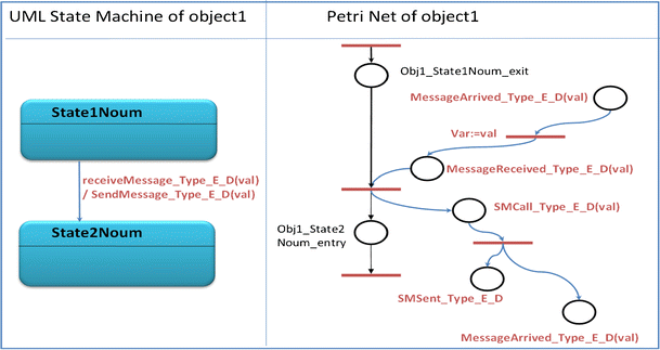
Transformation of a simple transition
-
✓ An effect is represented in the Petri net by three places and a transition: a first place to call the action, a transition that allows variables assignment (operator), a place to show that the message is sent and a place to declare that the message is arrived (Fig. 10).

Rule C3
A transition with a guard condition is transformed into two transitions in the Petri net. A predicate is attributed to each transition. The first predicate checks if the guard is true and the second predicate checks if the guard is false (Fig. 11).

Transformation rules of condition guard and choice
-
D-
Choice Pseudostate
Definition
Choice vertices which, when reached, result in the dynamic evaluation of the guards of the triggers of its outgoing transitions. This realizes a dynamic conditional branch. It allows splitting of transitions into multiple outgoing paths such that the decision on which path to take may be a function of the results of prior actions performed in the same run-to-completion step. If more than one of the guards evaluates to true, an arbitrary one is selected. If none of the guards evaluates to true, then the model is considered ill-formed. (To avoid this, it is recommended to define one outgoing transition with the predefined “else” guard for every choice vertex.)
Rule D
In our study, the choice has two outgoing transitions with two guards. So the choice is transformed into two transitions in the corresponding Petri net. A predicate is associated to each transition representing guards of the state machine (Fig. 11).
4.3 Start Of Mission (SOM) Application
The ERTMS system is composed of two parts, on-track and on-board equipment. It is necessary to consider two system points of view in order to identify external actors. In the first point of view, the considered system is the on-board one, so actors are defined as driver, RBC, and GSM-R. In the second point of view, the considered system is the trackside one, so actors are defined as trains (EVCs), traffic manager, and interlocking. This allows defining system use cases which are a sequence of actions carried out by the system and producing an observable result for a particular actor. The first point of view was chosen in order to comply with the research aim and to check the EVC component. Therefore, a complete use case must be modelled in order to use it for verification and validation. The table of requirements used to model this procedure is available in [33]. This procedure is a use case for the on-board system and needs to be detailed in a State machine diagram in order to understand the dynamic behaviour of the EVC.
4.3.1 The UML modelling of SOM procedure
The procedure Start of Mission (SOM) allows the start of a train and it is triggered by the driver in these cases: Once the train is awake, or once shunting movements are finished, or once a mission is ended, or once a slave engine becomes a leading engine. The common point of all these situations is that the ERTMS/ETCS on-board is in Stand-By mode, but the Start of Mission will be different, since some data may be already stored on-board, depending on the previous situation. Once the ERTMS/ETCS on-board equipment is in Stand-By mode, the start of mission is not the only possibility; the engine may be remote controlled (sleeping). At the beginning of the Start of Mission procedure, the data required may be in one of three states: “valid” (the stored value is known to be correct) or “Invalid” (the stored value may be wrong) or “Unknown”. This refers to the following data: Driver ID, ERTMS/ETCS level, RBC ID/phone number, Train Data, Train Running Number and Train Position.
The State machine diagram presented in this section (Fig. 12) describes the behaviour of the EVC during the identification of SOM data.

A UML State Machine of SOM Data Identification [33]
4.3.2 The transformation of SOM model into Petri net
In order to apply the different transformation rules, we choose at first, to transform a simple part of the UML State machine (Fig. 12), the identification of the driver (Fig. 13). In fact, the Start of Mission procedure shall be engaged when the ERTMS/ETCS on-board equipment is in Stand-By mode with a desk open and if no pending communication session and/or radio safe connection is established. After, depending on the stored status of the Driver-ID, the ERTMS/ETCS on-board equipment shall request the driver to enter the Driver-ID (if the status of Driver-ID is unknown) or shall request the driver to revalidate or re-enter the Driver-ID (if the status of the Driver-ID is invalid). Then, the ERTMS/ETCS on-board equipment shall check if the entered Driver-ID is valid or invalid. In the case of a valid DI, the ERTMS/ETCS on-board equipment updates the stored DI. In the case of a stored valid DI, it is possible to check the status of the Train running number (TRN).

A UML state machine of driver identification
The application of our defined transformation rules allows obtaining the Petri Net shown in Fig. 14.

The obtained Petri net of driver identification part after the UML model transformation
5 Test scenarios generation
5.1 Approach
A test scenario is considered as a firing sequence in the Petri net. So, the test scenarios generation corresponds to the generation of firing sequences in the reachability graph. Various methods have been suggested to handle the PN reachability problem. In this paper, we are interested in the Petri net logical abstraction technique proposed initially by Benasser [2]. This method consists of developing a unique sequence of partial steps corresponding to the total behaviour of the system. The proposal approach was validated on several examples using logical constraint programming techniques. Numerical results using Prolog IV have shown that the method can be more effective than other generic solvers. However, the practical resolution performance is limited by the incremental search mechanism used: memory overflows appear early when the size of the problem grows.
If we recall the definition 1 of Section 4.2.2, we add the definition of the following matrices: Precondition (Pre: m × n), Postcondition (Post: m × n) and Incidence (C: m × n).

In a Petri net, the markings of places represent the state of the corresponding system at a given moment. This marking can be modified according to the firing of transitions. A transition t is firable for a marking m0 (denoted by m0 [t〉), when ∀ p ∈ P, m0 (p) ≥ W (p, t). If this condition is satisfied, a new marking m1 is produced from the marking m0 (denoted by m0 [t〉m1): ∀ p ∈ P, m1 (p) = m0 (p) − W (p, t) + W (t, p).
The reachability graph corresponds to the usual formal representation of the behaviour of the net. The reachability graph of a net R, denoted by G(R, m0), is defined by:
-
✓ A set of nodes A(R, m0) which represent all the markings reachable by any firable transition sequence. Formally, A(R, m0) = {mf|∃ σ ∈ T (R, m0) s.t. m0[σ〉 mf };
-
✓ A set of arcs, where an arc (mi, mj) labelled t connects nodes representing the markings mi and mj if mi [t〉 mj.
Practically, it is not possible to explore the reachability graph exhaustively because of the well known problem of combinatorial explosion: the size of the state-space may grow exponentially with the size of a system configuration. Many methods have been studied to master this explosion; we cite the three main approaches:
-
✓ The first one consists of managing the combinatorial explosion without modifying the studied reachability graph. Classical approaches are graph compressions and forward checking [9, 10].
-
✓ Other techniques construct a reduced reachability graph associated to the original, based on some properties to preserve [4, 12].
-
✓ The last ones are based on the state equation: we can distinguish parameterized analysis and algebraic methods [18].
In the following section, we propose new approaches to find firable transitions sequences leading to a target marking. Our methods are based on the Petri net logical abstraction and mathematical programming techniques.
5.2 Test generation
Benasser [2] proposed an algorithm to solve the reachability problem using the logical abstraction and constraint programming techniques. This algorithm iterates the number of partial steps used, adding one new step at each iteration, in order to test all the lengths of complete sequences of partial steps lower than K.
This algorithm is correct since the sequences found are effectively sequences of steps which produce the desired final marking. It is also complete since it can enumerate all the solutions of length lower than a given integer. In each iteration, the algorithm uses a mechanism of linear constraints solving. It has been implemented using the constraint logic programming software Prolog IV. The interest of the use of Prolog IV lies in the fact that its constraints resolution mechanism is incremental [15]. Indeed, it is not necessary to redefine in each iteration the constraints incorporated into the previous stage. The constraints are added in the constraints solver so that it can reuse the results of the previous constraints propagation. The search for the concrete results is made at the end by an enumeration of all the possible integer solutions.
In the previous figure (Fig. 15), we show how to generate sequences from resulted Petri net (transformation of UML diagram in Fig. 14). The Pre and Post matrices are generated in order to be used for sequences generation. Indeed, as shown in Fig. 15, we can generate sequences with fixed length for all final markings. We can also generate sequences whose maximum length is l. The final marking can be also fixed. In this case, all possible sequences, which can reach this final marking, are generated.

Sequences generation example
5.3 Simulation
The scenarios obtained from the sequences generation method, will be tested on the ERTMS platform simulator in order to check the components. INRETS’s ERTMS simulation platform consists of the following components:
-
▪ A single train operational simulator with its 3D visualization of the tracks
-
▪ An ERTMS traffic simulator:
-
▪ a route map controller;
-
▪ an interlocking system
-
▪ up to 2 Radio Block Centres
-
▪ up to 11 trains including the operational train simulator
-
-
▪ Off-line tools:
-
▪ A track editor for constructing tracks and a set of elements of the tracks (track, points, balises, boards...)
-
▪ A scenario editor for setting the dynamic parameters of each scenario.
-
Both the train operational simulator and traffic simulator can be used stand alone or interconnected to put the train driver in a simulated traffic (Fig. 16). They use the same offline tools so tracks can be used either for traffic or operational train scenarios.

The DMI of the train operational simulator with its 3D
6 Conclusions
In this paper, we developed a methodology of test scenarios generation. At a first step, we formalized specification by a using a transformation technique of UML models. The obtained Petri net models are used in order to generate test scenarios. One scenario is considered like a firing sequence in the reachability graph. So, we developed a method allowing generation of firing sequences from an initial marking to a final marking.
Generally, the number of tests is directly linked with the product of its amount of functions and the degree of freedom of its application conditions. It means the more flexible is the solution the biggest is the number of tests and its related costs. The approach, developed in this paper, has been applied to components of a flexible system ERTMS (European Rail Traffic Management System) in order to demonstrate the validation and certification costs reduction and also to minimize the upgrade and retrofit constraints and validation cost.
In future work, we take into account the time in order to formalize specifications. In ERTMS context, interactions may be related to time constraints. A transformation of UML models based on time constraints is interesting. Then, the coverage of the generated test scenarios must be defined. In this paper, we generate a set of test scenarios from the reachability graph accessibility based on constraint programming. Later we want to define a coverage criterion to ensure that tests adequately cover the specification
References
Baudoin C, Hollowell G (1996) Realizing the object-oriented lifecycle. Prentice Hall, Upper Saddle River
Benasser A (2000) “L’accessibilité dans les réseaux de Petri : une approche basée sur la programmation par contraintes”, PhD thesis, Université des sciences et technologies de Lille
Bernardi S, Donatelli S, Merseguer J (2002) From UML Sequence Diagrams and Statecharts to analysable Petri Net models, In Proc. of the 3rd Int. Workshop on Software and Performance (WOSP), pp 35–45, Rome, Italy, July
Berthelot G (1986) Transformations and decompositions of nets. In: Brauer W, Reisig W, Rozenberg G (eds) Advances in Petri Nets 1986 Part I. Proceedings of an Advanced Course 254:359–376
Booch G (1991) Object Oriented Design with Applications, Redwood City, CA:Benjamen/Cummings
Coad P, Yourdon E (1991) Object-oriented analysis, 2nd edn. Yourdon Press, Prentice Hall, Englewood Cliffs
European Commission (2006) ERTMS – Delivering flexible and reliable rail traffic, DG TREN,16p
European Communities Commission (2001) Council Directive 2001/16/EC of the European Parliament and of the Council on the interoperability of the trans-European conventional rail system, Official Journal of the European Union
Fernandez JC, Jard C, Jéron T, Mounier L (1992) On the fly verification of finite transition systems. Formal Methods in System Design
Gunnarsson J (1998) Symbolic tools for verification of large scale DEDS. IEEE Int. Conf. on Systems, Man, and Cybernetics (SMC’98), 11-14 October 1998, SanDiego, CA, pp 722–727
Hopkins R, Smith M, King P (2002) Two approaches to integrating UML and performance models. In Proc. of the 3rd Int. Workshop on Software and Performance (WOSP), pp 91–92, July
Huber P, Jensen AM, Jepsen LO, Jensen K (1985) Towards reachability trees for high-level Petri nets, Lecture Notes in Computer Science: Advances in Petri Nets 1984, 188:215–233
Jabri S, Lemaire E (2007) Modeling of the European railway system for automatic checking”, 15th International Symposium EURNEX- ZEL 2007: Towards more competitive European rail system
Jacobson I (1987) Object Oriented development in an industrial environment, Proceedings on Object-Oriented programming systems, languages and applications, pp 183-191
Jaffar J, Michaylov S, Stuckey P, Yap R (1992) The CLP (R) language and system. ACM Trans Program Lang Syst 14(3):339–395
King P, Pooley R (1999) Using UML to derive stochastic Petri net models. In Proceedings of the 15th UK Performance Engineering Workshop, pp 45–56, Bristol, UK, July
El Koursi EM, Kampmann B (2002) Qualitative and quantitative safety assessment of ERTMS Operating rules. Comprail, pp 671-680
Lautenbach K (1987) Linear algebraic techniques for place/transition nets. In Advances in Petri Nets 1986, Part I, Proceedings of an Advanced Course, 254:142–167
Lochman L (2009) Background for ERTMS. In: IUC (ed) Compendium on ERTMS
Lopes D, Hammoudi S, Bezivin J, Jouault F (2005) Mapping Specification in MDA: From Theory to Practice. Proceedings of INTEROPESA, pp 253-264
Lopez-Garo JP, Merseguer J, Campos J (2004) From UML activity diagrams to stochastic Petri Net models: Application to Software Performance Engineering. Proceedings of the 3rd Int. workshop on Software and performance, pp 25-36
Marsan MA, Balbo G, Conte G, Donatelli S, Franceschinis G (1995) Modelling with Generalized Stochastic Petri Nets. Series in parallel computing. Wiley
Merseguer J (2004) On the use of UML State Machines for Software Performance Evaluation, In Proc. of the 10th IEEE Real-Time and Embedded Technology and Applications Symposium (RTAS)
Murata T (1989) Petri nets: Properties, analysis and applications. Proc IEEE 77(4):541–574
Object Management Group (2005) Unified Modelling Language: superstructure, version 2.0 http://www.omg.org
Pettit RG, Gomaa H (2000) Validation of Dynamic Behavior in UML Using Colored Petri Nets, Workshop on Dynamic Behavior in UML Models: Semantic Questions
Pooley R, King P (1999) The Unified Modelling Language and Performance Engineering. In IEE Proceedings - Software, volume 146(2), March
Rumbaugh J, Blaha M, Premerlani W, Eddy F, Lorensen W (1997) OMT, Tome1 : Modélisation et conception orientées Objet, Dunod
Samuel P, Mall R, Kanth P (2007) Automatic test case generation from UML communication diagrams. Inf Softw Technol 49:158–171
Shlaer S, Mellor S (1988) Object-oriented systems analysis. Yourdon Press Computing Series
Trowitzsch J, Zimmermann A (2006) Using UML state machines and Petri nets for the quantitative investigation of ETCS. Proceedings of the 1st Int. conference on Performance evaluation methodologies and tools, Italy
UNISIG, ERTMS Users Group (1999) FRS V4.29, Functional System Requirements Specification, FRS
UNISIG, ERTMS Users Group (2008) Subset026-5, System Requirements Specification, SRS
Wendler E (2009) Influence of ETCS on the capacity of lines. In: UIC (ed) Compendium on ERTMS
Winter P (2009a) Train control-command: the ETCS developments. In: UIC (ed) Compendium on ERTMS
Winter P (2009b) European ERTMS applications in commercial operation. In: UIC (ed) Compendium on ERTMS
Winter P (2009c) Conclusions and outlook. In: UIC (ed) Compendium on ERTMS
Yourdon E, Constantine L (1979) Structured Design. Prentice Hall, Englewood Cliffs
Open Access
This article is distributed under the terms of the Creative Commons Attribution Noncommercial License which permits any noncommercial use, distribution, and reproduction in any medium, provided the original author(s) and source are credited.
Author information
Authors and Affiliations
Corresponding author
Rights and permissions
Open Access This article is distributed under the terms of the Creative Commons Attribution 2.0 International License (https://creativecommons.org/licenses/by/2.0), which permits unrestricted use, distribution, and reproduction in any medium, provided the original work is properly cited.
About this article
Cite this article
Jabri, S., El Koursi, E.M., Bourdeaud’huy, T. et al. European railway traffic management system validation using UML/Petri nets modelling strategy. Eur. Transp. Res. Rev. 2, 113–128 (2010). https://doi.org/10.1007/s12544-010-0030-5
Received:
Accepted:
Published:
Issue Date:
DOI: https://doi.org/10.1007/s12544-010-0030-5